Use Case Diagram Dependency Example
What is UML Relationship?
Relationships in UML are used to represent a connection between structural, behavioral, or grouping things. It is also called a link that describes how two or more things can relate to each other during the execution of a system. Type of UML Relationship are Association, Dependency , Generalization , and Realization.
Lets study them in detail

Association
It is a set of links that connects elements of the UML model. It also defines how many objects are taking part in that relation.
Dependency
In a dependency relationship, as the name suggests, two or more elements are dependent on each other. In this kind of a relationship, if we make a change to a particular element, then it is likely possible that all the other elements will also get affected by the change.
Generalization
It is also called a parent-child relationship. In generalization, one element is a specialization of another general component. It may be substituted for it. It is mostly used to represent inheritance.
Realization
In a realization relationship of UML, one entity denotes some responsibility which is not implemented by itself and the other entity that implements them. This relationship is mostly found in the case of interfaces.
In this UML tutorial, you will learn:
- Association
- Dependency
- Generalization
- Realization
- Composition
- Aggregation
Association
It is a structural relationship that represents objects can be connected or associated with another object inside the system. Following constraints can be applied to the association relationship.
- {implicit} – Implicit constraints specify that the relationship is not manifest; it is based upon a concept.
- {ordered} – Ordered constraints specify that the set of objects at one end of an association are in a specific way.
- {changeable} – Changeable constraint specifies that the connection between various objects in the system can be added, removed, and modified as per the requirement.
- {addOnly} – It specifies that the new connections can be added from an object which is situated at the other end an association.
- {frozen} – It specifies that when a link is added between two objects, then it cannot be modified while the frozen constraint is active on the given link or a connection.
We can also create a class that has association properties; it is called as an association class.
Reflexive association
The reflexive association is a subtype of association relationship in UML. In a reflexive association, the instances of the same class can be related to each other. An instance of a class is also said to be an object.
Reflexive association states that a link or a connection can be present within the objects of the same class.
Let us consider an example of a class fruit. The fruit class has two instances, such as mango and apple. Reflexive association states that a link between mango and apple can be present as they are instances of the same class, such as fruit.
Directed association
As the name suggests, the directed association is related to the direction of flow within association classes.
In a directed association, the flow is directed. The association from one class to another class flows in a single direction only.
It is denoted using a solid line with an arrowhead.
Example:
You can say that there is a directed association relationship between a server and a client. A server can process the requests of a client. This flow is unidirectional, that flows from server to client only. Hence a directed association relationship can be present within servers and clients of a system.
Dependency
Using a dependency relationship in UML, one can relate how various things inside a particular system are dependent on each other. Dependency is used to describe the relationship between various elements in UML that are dependent upon each other.
Stereotypes
- «bind» – Bind is a constraint which specifies that the source can initialize the template at a target location, using provided parameters or values.
- «derive» – It represents that the location of a source object can be calculated from the target object.
- «friend» – It specifies that the source has unique visibility in the target object.
- «instanceOf» – It specifies that the instance of a target classifier is the source object.
- «instantiate» – It specifies that the source object is capable of creating instances of a target object.
- «refine» – It specifies that the source object has exceptional abstraction than that of the target object.
- «use» – It is used when packages are created in UML. The use stereotype describes that the elements of a source package can be present inside the target package as well. It describes that the source package makes use of some elements of a target package.
- «substitute» – specifies that the client may be substituted for the supplier at runtime.
- «access» – It specifies that the source package access the elements of the target package which is also called as a private merging.
- «import» – It specifies that the target can import the element of a source package like they are defined inside the target which is also called as a public merging.
- «permit» – specifies that source element has access to the supplier element whatever the declared visibility of the supplier.
- «extend» – Helps you to specifies that the target can extend the behavior of the source element.
- «include» – Allows you to specifies the source element which can be included the behavior of another element at a specified location. (same as a function call in c/c++)
- «become» – It specifies that the target is similar to the source with different values and roles.
- «call» – It specifies that the source can invoke a target object method.
- «copy» – It specifies that the target object is independent, copy of a source object.
- «parameter» – the supplier is a parameter of the client operations.
- «send» – the client is an operation that sends the supplier some unspecified target.
Stereotypes among state machine
- «send» – Specifies that the source operation sends the target event.
Generalization
It is a relationship between a general entity and a unique entity which is present inside the system.
In a generalization relationship, the object-oriented concept called inheritance can be implemented. A generalization relationship exists between two objects, also called as entities or things. In a generalization relationship, one entity is a parent, and another is said to be as a child. These entities can be represented using inheritance.
In inheritance, a child of any parent can access, update, or inherit the functionality as specified inside the parent object. A child object can add its functionality to itself as well as inherit the structure and behavior of a parent object.
This type of relationship collectively known as a generalization relationship.
Stereotypes and their constraints
- «implementation» – This stereotype is used to represent that the child entity is being implemented by the parent entity by inheriting the structure and behavior of a parent object without violating the rules.Note This stereotype if widely used in a single inheritance.
Generalization relationship contains constraints such as complete, incomplete to check whether all the child entities are being included in the relationship or not.
Realization
In a realization relationship of UML, one entity denotes some responsibility which is not implemented by itself and the other entity that implements them. This relationship is mostly found in the case of interfaces.
Realization can be represented in two ways:
- Using a canonical form
- Using an elided form
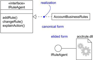
Realization in UML
In the above diagram, account business rules realize the interface IRuleAgent.
Types of realization:
- Canonical form: In a realization relationship of UML, the canonical form is used to realize interfaces across the system. It uses an interface stereotype to create an interface and realization relationship is used to realize the particular interface.In a canonical form, the realization relationship is denoted using the dashed directed line with a sizeable open arrowhead.In the above diagram, interface Iruleagent is realized using an object called as Account Business Rules.
- Elided form: Realization in the UML class diagram can also be shown using an elided form. In an elided form, the interface is denoted using a circle which is also called as a lollipop notation.This interface, when realized using anything present inside the system, creates an elided structure.In the above diagram, the interface Iruleagent is denoted using an elided form which is being realized by acctrule.dll.
Composition
It is not a standard UML relationship, but it is still used in various applications.
Composite aggregation is a subtype of aggregation relation with characteristics as:
- it is a two-way association between the objects.
- It is a whole/part relationship.
- If a composite is deleted, all other parts associated with it are deleted.
Composite aggregation is described as a binary association decorated with a filled black diamond at the aggregate (whole) end.

Composition in UML
A folder is a structure which holds n number of files in it. A folder is used to store the files inside it. Each folder can be associated with any number of files. In a computer system, every single file is a part of at least one folder inside the file organization system. The same file can also be a part of another folder, but it is not mandatory. Whenever a file is removed from the folder, the folder stays un-affected whereas the data related to that particular file is destroyed. If a delete operation is executed on the folder, then it also affects all the files which are present inside the folder. All the files associated with the folder are automatically destroyed once the folder is removed from the system.
This type of relationship in UML is known by composite aggregation relationship.
Aggregation
An aggregation is a subtype of an association relationship in UML. Aggregation and composition are both the types of association relationship in UML. An aggregation relationship can be described in simple words as " an object of one class can own or access the objects of another class."
In an aggregation relationship, the dependent object remains in the scope of a relationship even when the source object is destroyed.
Let us consider an example of a car and a wheel. A car needs a wheel to function correctly, but a wheel doesn't always need a car. It can also be used with the bike, bicycle, or any other vehicles but not a particular car. Here, the wheel object is meaningful even without the car object. Such type of relationship is called an aggregation relation.
Summary
- Relationship in UML allows one thing to relate with other things inside the system.
- An association, dependency, generalization, and realization relationships are defined by UML.
- Composition relationship can also be used to represent that object can be a part of only one composite at a time.
- Association is used to describe that one object can be associated with another object.
- Dependency denotes that objects can be dependent on each other.
- A realization is a meaningful relationship between classifiers.
- Generalization is also called as a parent-child relationship.
Use Case Diagram Dependency Example
Source: https://www.guru99.com/uml-relationships-with-example.html
0 Response to "Use Case Diagram Dependency Example"
Post a Comment